
Land Surveying and Land Development Software for Land Surveyors, Engineers, Architects and Construction
Import point file and Make DTM tutorial
THIS IS A TUTORIAL TO IMPORT A POINT FILE
AND CREATE A DIGITAL TERRAIN MODEL.
You will need to download this point file to use: Point file
You may download this drawing to use: Drawing
First we will set the drawing settings:
We will use metric units and a ratio of 250.
From the pull down menu select: Drafting-) Drawing setup
Select units English or Metric: (E or M) M
Enter ratio of drawing 1: 250
Text size has been set to 3mm
You can download your data collector to an ascii point file in the following format:
P,E,N,Z,D
Now we will import an ascii point file.
DPpoints-)Import points-)PENZD
Now browse and select the DTMmetTUT.asc file that you downloaded from above.
Enter 1 for comma delimited file, Enter 2 for space delimited file: 1
Lets zoom extents to see the points.
Command: 'ZOOM
Zoom: In/Out/All/Center/Extents/Left/Previous/Right/Window/Scale (nX/nXP): E
Lets turn on the point nodes.
DPpoints-)Point utilities-)Point display on
Now we will create a surface model of the points.
We will create a project from DP nodes.
DPdtm-)Create project-)create from DP nodes
getxyz loaded.
Select entities: Select all the points
Opposite corner:
Entities in set: 146
Select entities: Press enter
You now must give a name for the file (and remember where you put it).
Now we will open the project that we just made.
DPdtm-)Open project
Browse to the file that you just created.
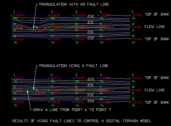
If you want to draw and select fault lines (not needed for this example):
DPdtm-)Select fault lines. (we will not use this command in this example)
See the example of using fault lines to control a digital terrain model at the bottom of this page.
You may draw a boundary around the points.
As you can see from the sample drawing, this boundary is a closed polyline that is drawn through the nodes of the points that represent the boundary of the model.
This boundary is optional - but it will prevent any triangulation outside of it.
DPdtm-)Select boundaries.
Now select the polyline.
Now we will create a surface.
DPdtm-)Create surface
A dialog box appears.
If we have made a fault line file or a boundary file we may check the box to use them in making the surface.
Place a check in the box next to: Use Bounding/Void Polygon(s)
You will see there is a path to the file there already.
Click OK to create the surface.
Command: dptriangulateTriangulation Percent Complete: 100%
Now we will create contours:
DPdtm-)Create contours
A dialog box will appear. There are several option for you to set as you like.
We will set the contour interval to 0.25 and the Index interval to 1.
Click OK to create contours.
Change the layer colors and linetype as you wish.
You may also import a TIN or a Mesh if choose to do so.
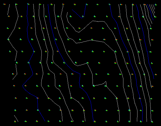
Your drawing should look like this:
RESULTS OF USING FAULT LINES TO CONTROL A DIGITAL TERRAIN MODEL:
Copyright © 2024 CogoSoftware. Powered by Zen Cart