Sewer Profiles
SEWER PROFILES
Sewer Profiles is a drafting aid for drawing profiles of pipes and manholes.
To begin Sewer Profiles, Select DProad -> Sewer profiles.
PLACE STRUCTURE
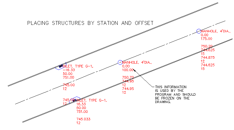
Select an alignment (line, arc, or
polyline) and place inlets, inlet manholes or manholes by station and offset.
The blocks that are placed in the drawing are in the Dpsew directory and may be
edited or redefined to meet your personal needs. Be sure to save a copy before
you change them. The names must stay the same for the program to find them.
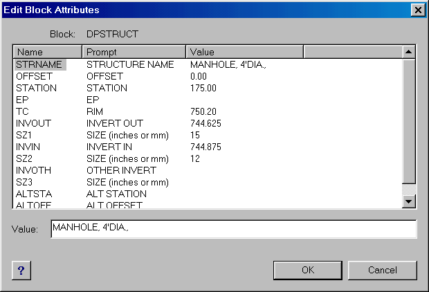
When a structure is placed in the drawing a data block is also placed at the
same point (dpstruct.dwg). The name, station and offset fields will be
filled in automatically. You must fill in the rest of the data that you
need (rim, inverts, pipe size, etc.). Type DDATTE at the command prompt,
select the block and add or change any of the data. The alternate station
and offset fields are to be used when a structure that is stationed along one
alignment is the first structure along another alignment (a manhole at a street
intersection for example). If this structure is selected first, the Draw
profile and Write text commands will ask if you wish to use the alternate
stationing.

If you do not use the Place Structure command you will have to place the block (dpstruct.dwg) on each of the structures in the drawing using Autocad's, or Intellicad's DDINSERT command. Use Autocad's, or Intellicad's DDATTE command to edit all needed data in the block.
NOTE: After using the blocks, the layer DP_STRUCTURE may be frozen to hide the data from being viewed in the drawing.
End sections or headwalls will have to be
drawn by the user. Place the block (dpstruct.dwg) at the center of the
structure. If the word END, HDWL, or HEADWALL appears in the structure
description, a triangular shape will be drawn in the profile. Add the pipe
diameter to the invert elevation for the rim elevation (the top of the end
section or headwall).
SELECT STRUCTURES
After all necessary data has been added to
the block (dpstruct.dwg) You may select the blocks by picking any part of the
visible data text. Select from left to right in the order that you wish to have
the profile drawn, or you may select in the order that you wish the note to be
written.
NOTE: Structures must be selected before a
profile can be drawn, or a note written.
CREATE PROFILE UCS
Before drawing a profile you will need to
set up a profile coordinate system. Use the Create profile UCS button, select a
known point, enter station and elevation of known point and a name for the UCS.
Be sure the scales are set correctly.
SELECT PROFILE UCS
The Select UCS button may be used for
moving between the profile UCS and the plan (world) UCS.
DRAW PROFILE
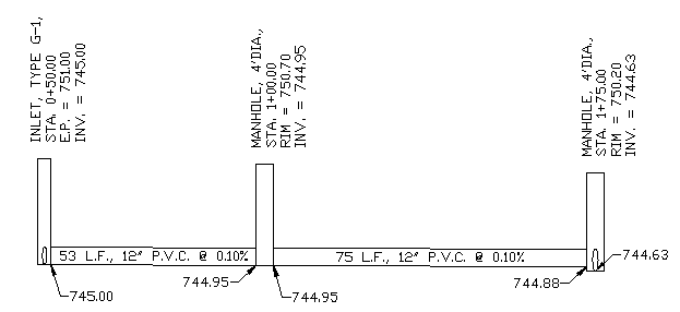
Select the Draw profile button and a
profile is automatically drawn. If follow alignment is toggled on, the profile
will be drawn along the alignment. If follow sewer is toggled on, the profile
will start at the station of the first structure and measure the distance to
the next structure. If the label buttons are toggled on the labels will appear
on their own layers. The profile will be drawn on the current layer. Notations
will use the current units precision settings of the drawing, set them to the
desired number of decimal places before drawing a profile. Labels will
use the current text style.
NOTE: Pipe lengths are calculated from
center to center of structure (the placement point for dpstruct.dwg) and are
used to calculate the slope.
WRITE TEXT
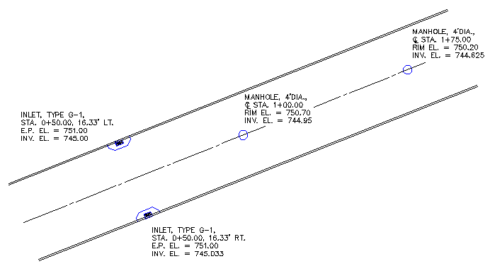
After one or more structures are selected
the Write text command will write a text note of the structure which will be
placed on the current layer. Text will be written with the current text style.
The note will be formatted as follows:
NAME OF STRUCTURE
STATION, OFFSET
RIM (if manhole) E.P. (if inlet)
INVERT OF STRUCTURE


This profile was generated automatically by
selecting the desired structures in the plan above

These plan notes were generated automatically by
selecting the desired structures in the plan above
